20+ bgp topology diagram
The Physical topology depicts a switch and four hosts in two different VLANs Host A and Host B are in VLAN 20 and Host C and Host D are in VLAN 30. Clos Topology Properties The following are some key properties of the Clos topology.
![]()
The State Transition Graph For The Bgp System Described In Fig 1 Download Scientific Diagram
When BGP is used in the context of Azure virtual networks it enables the Azure VPN gateways and your on-premises VPN devices known as BGP peers or neighbors.

. Only the networks in RIB-Failure condition which have a different next-hop in BGP than its same entry in Routing Table are suppressed with the bgp suppress-inactive command. VXLAN bridging is enabled by mapping VLAN to VNIs as detailed in the diagram. Router A has no choice but to put the 2021024 route into active state and query its neighbor Router B.
Right side leaves are MLAG leaves and have SVI 10 in VRF-Blue. Routing is a basic concept in data communication networks. Sample Configurations EVPN VXLAN IRB Sample Configuration In the topology below we are connecting a Layer 2 site with a Layer 3 site using Layer 3 EVPN type-5 route.
In this diagram VLAN 20 contains the 10020024 network. On Router R2 routes are shown in the BGP table in RIB-Failure condition. Multi-Tiered Routing Architecture.
Acl arp ASA BGP CCNA CCNP cisco Cryptography eigrp Encryption hashing nat networking ospf routing subnetting TLS vlans VPN. 110 messages 0 Topology. Instead of a physical device or appliance each Cloud Router consists of software tasks that.
Power to quarantine stock etc. 5Power to order seizure of stock etc. In other words you should.
Configure BGP for a VPN gateway. Ill use the following topology for this. O The topology is fully non-blocking or more accurately non- interfering if M N and oversubscribed by a factor of NM otherwise.
Routing is an activity that transmits information from a source address to a destination address through an interconnected network. The official name of a diagram that shows the different states and we can move from one state to another is called a FSM Finite State Machine. RRshow ip bgp update-group 3 BGP version 4 update-group 3 internal Address Family.
IPv4 Unicast BGP Update version. Cloud Router is a fully distributed and managed Google Cloud service that uses the Border Gateway Protocol BGP to advertise IP address ranges. Add a TCP header 20 bytes and IP header 20 bytes and you have a 1500 byte packet.
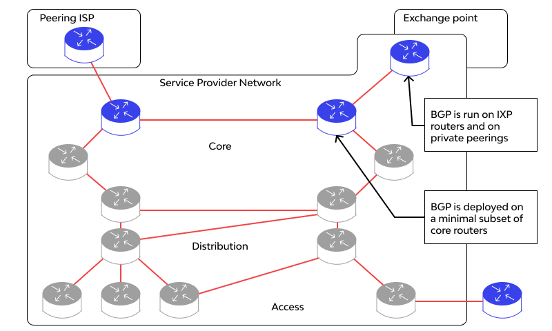
Routing occurs at the network layer Layer 3 in the Open Systems Interconnection OSI reference model. Tier-0 SR does routing lookup and sends the packet to the physical router following the BGP route which routes it to 192. The following diagram shows the multi-tiered routing architecture.
The 2021024 route has gone active for 1 minute and 12 seconds and the neighbor that has not responded is listed as 10112 from Serial0 which is Router B. Notice the output of show ip eigrp topology active in Router A. FastEthernet00 20111 YES manual up up.
135 Link-State Routing-Update Algorithm. Notice of disease or suspected disease to be given 4. It programs custom dynamic routes based on the BGP advertisements that it receives from a peer.
6BANK SECRECY ACT ANTI-MONEY LAUNDERING. Next step is to verify the topology table using show ip bgp The topology table of R1 shows that next hop of 15011132 is 0000 with weight set to 0 meaning it is a locally generated route. Configuration Network Topology Diagram.
THE STOCK DISEASES ACT CHAPTER 252 OF THE LAWS OF ZAMBIA CHAPTER 252 THE STOCK DISEASES ACT THE STOCK DISEASES ACT ARRANGEMENT OF SECTIONS Section 1. 1721610024 and 1721620024 are seen as NSX Static routes on Tier-0 LR. The next hop for 15022232 is 101122 meaning the route has been learned from R2.
In the following topology. BGP AS Path Prepending AS Path is the fourth BGP attribute AS Path is well known mandatory attribute. Click on one of the buttons above to generate the configuration.
Configure the topology as per the diagram and assign the IP address as per the topology. Fill out all required fields under all the tabs or on the network diagram. Peering is settlement-free also known as bill-and-keep or sender keeps all meaning that neither party pays the other in association with the exchange of traffic.
Copy and paste the generated configuration output onto your SRX series or J series device in configuration mode. Here M and N is the uplink and downlink port count respectively for a Tier 2 switch as shown in Figure 2. Cloud Router overview.
For BGP it looks like this. Current working OK last not in list Refresh blocked not in list last not in list Update messages formatted 20 replicated 20 current. Serial30 1112 YES manual up up.
In computer networking peering is a voluntary interconnection of administratively separate Internet networks for the purpose of exchanging traffic between the down-stream users of each network. Our content testing team has validated and updated this example. 304 136 Routing on Other Attributes.
BGP is the standard routing protocol used on the internet to exchange routing and reachability information between two or more networks. Router bgp 65001 router-id. The devices that provide routing and forwarding.

Bgp Example Topology And Designations Download Scientific Diagram
![]()
Scenario Topology Of Bgp Multihoming And Transit As Problem Download Scientific Diagram

The Topology We Used In Our Bgp Experiments With Harmful Global Events Download Scientific Diagram
Is Bgp A Distance Vector Protocol Quora

Bgp Example Topology And Designations Download Scientific Diagram
Top 13 Bgp Interview Questions And Answers 2022

1 Bgp Protocol Illustration Download Scientific Diagram

Example Topology With Ibgp Full Mesh Download Scientific Diagram

Enabling Bgp 4 In A Network 34 Download Scientific Diagram
Top 13 Bgp Interview Questions And Answers 2022
Top 13 Bgp Interview Questions And Answers 2022

Network Topology Area The Local Area Network Lan Of Each Branch And Download Scientific Diagram
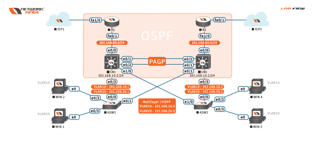
Ospf Bgp Network Diagram Download Scientific Diagram

Community Gns3

Vmware And Cisco Vlan Connection Iii An Example Ospf Bgp Routing Download Scientific Diagram

Network Topology In Gns3 For Mpls Bgp Network Architecture Download Scientific Diagram

Ospf Bgp Network Diagram Download Scientific Diagram